
Tern · project
Battery management & datalogging
An RS485 tap on your BMS that turns every charge and every dive into data — so a sagging string or a hot cell shows up before it fails 1500m from the exit.
It works, but it isn't repeatable yet.
What it is
Real-use data instead of test-stand data
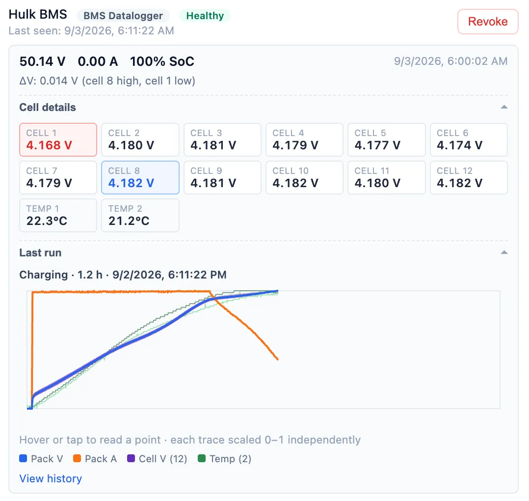
Run tests on a bench tell you what a pack does under controlled load. This tells you what your pack actually did on your last dive — current draw, cell spread and temperature, under real load, in the water. The conceptual problem it solves is surprise failures: a string sagging under load or running hotter than it should shows up in the data before it strands you mid-dive. Yet to be determined: is real data more valuable than controlled test data? Does live data from actual runs actually inform failure prediction?
What it isn’t
Not a BMS, and not a safety system
This doesn’t manage anything. It reads the BMS’s own RS485 port and logs what it says — no protection logic, no cutoffs, no ability to act on what it sees. Your BMS is still the thing keeping the pack safe; this is just a device that logs what the BMS is producing. The current setup typically allows you to check state of charge via wireless using an app -- that gives you a snapshot. The goal here is to log real data from the run, not just the start and end points.
How it works
Tap the port, wake on change, report even when it can’t see anything.
The build is deliberately simple: a transceiver on the BMS’s RS485 port and an ESP32 with a WiFi radio, assuming the housing already has >5 VDC available for it.
- 01
Tap the RS485 port
An SP3485 half-duplex transceiver sits on the BMS’s existing RS485 port, reading the register protocol most “smart BMS with Bluetooth app” boards already speak.
- 02
Wake, sample, decide
Full-rate logging while current is flowing or voltages are moving; a slow idle cadence the rest of the time, so a resting pack doesn’t fill the log with nothing.
- 03
Upload, or buffer and wait
Periodic batches go to Dive Map over WiFi. No WiFi in range yet? It keeps logging to flash and drains the backlog the moment a connection shows up.
- 04
Report even when it can’t see the BMS
A separate heartbeat runs whether or not the last read succeeded, so a bad joint or an open line names itself on the website instead of looking identical to a pack that’s simply resting.
The build is fantastically simple — with one real requirement. If your BMS exposes RS485 and the housing has >5 VDC available inside it, this is a short parts list and an afternoon, not a project. That requirement is also the whole reason it isn’t universal: a BMS without RS485 has nothing here to tap.
What it catches
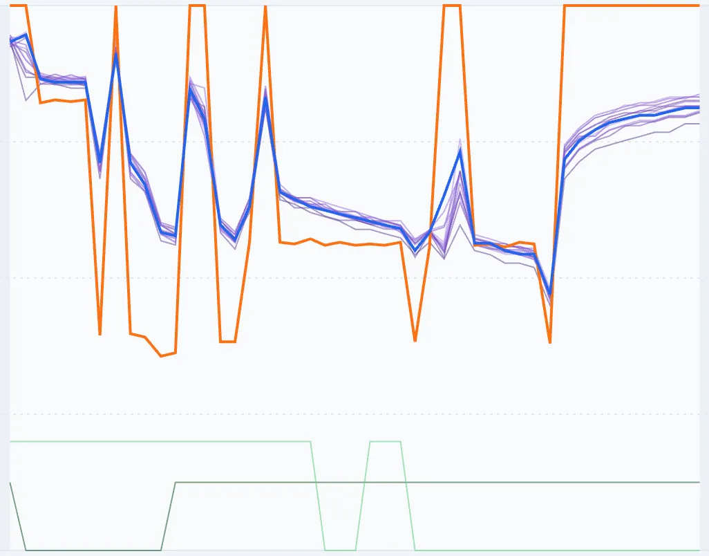
Multiple charge/discharge cycles, overlaid.
Every cycle logged is another trace on top of the last. A string that’s starting to sag relative to its own history is visible long before it would show up on a test stand — because this is testing the pack with the load it actually sees.
Specs
What’s on the breadboard today.
| Sensor link | RS485 onto the BMS’s existing port through a SparkFun SP3485 half-duplex transceiver, reading the JBD/Xiaoxiang “DD…77” register protocol — also confirmed working, unmodified, on LLT Smart BMS packs. |
|---|---|
| What it logs | Pack voltage, pack current, every cell voltage, 2–3 temperature sensors, state of charge, remaining and nominal capacity, cycle count, protection bits and FET status. |
| Processing | Adafruit HUZZAH32 Feather (ESP32). Wakes, polls the BMS over RS485, and decides whether to stay awake and log at full rate or go back to sleep. |
| Sample cadence | Every 10 s while something’s actually happening — current flowing, voltage moving. Otherwise a 30 s idle wake, checkpointed every 50 wakes, so a resting pack barely touches the log. |
| Uplink | WiFi captive-portal provisioning, then periodic upload to Dive Map over the same device-auth flow DPV-Nav uses. Offline, an onboard buffer holds roughly 5.5 hours of continuous full-rate logging. |
| Health reporting | A heartbeat on its own timer, never gated on a successful BMS read — so a dead RS485 joint shows up as a bad status on the website instead of looking exactly like a pack that’s just resting. |
| Power requirement | Needs the BMS’s RS485 port and >5 VDC available inside the housing. That’s the entire install requirement. Early installs used a separate battery instead of tying in to the BMS through a voltage regulator, but that’s not a great path. |
Roadmap
Where this is going.
Directional, not promised. The further right, the more likely it changes.
Now
Actively being built or tested
- Breadboard prototype wired into the scooter, reading the pack over RS485 every charge and every dive
- Telemetry, offline buffering, WiFi provisioning and cloud upload to Dive Map all working end to end
- A passive health badge on the device’s Dive Map tile, so a bad joint or a brownout loop shows up remotely instead of needing a tethered serial capture to find
Next
Committed, not started
- A KiCad board. Right now the whole build is breadboard wiring tucked into the housing — this is the actual “build one” milestone
- Publish the BOM and fab data once the board exists, alongside the build docs that make the repo worth opening
Later
Directional, may change
- Turn raw logged rows into something closer to a verdict — “this string is sagging relative to its own baseline” instead of a table you have to read yourself
- Whatever BMS protocol variants show up beyond the JBD/Xiaoxiang family already confirmed working
Open problem. Clean power inside the housing. Early bring-up found a BMS→ESP32 buck regulator that kept back-feeding the rail even after being “disconnected,” browning the board out intermittently — now understood, but the final clean power path still needs to land on the KiCad board rather than live as a lesson in a markdown file.
Source & docs
Build one.
This one is built from a handful of off-the-shelf parts — an ESP32 dev board, an RS485 transceiver breakout, and whatever power conversion your housing already needs. No custom PCB yet, which is exactly the gap the roadmap above is closing.
The source isn't public yet. It opens when Battery management & datalogging is far enough along that you could genuinely copy the work — a repository you can't build from is just a pile of files. What it's waiting on: a KiCad board — right now this is breadboard wiring tucked into a housing, not something you could follow along and build.
Licensing
How you may use it.
Fully open-source — no noncommercial carve-out; exact license TBD
Unlike some other Tern work, this one is meant to be fully open-source — no intent to sell it, and no noncommercial carve-out. The specific license is still to be finalized (expect something permissive, MIT/Apache-class, rather than the CC BY-NC-SA terms used elsewhere), but the direction is settled even while the repo stays private. The repo is currently private simply because I'm not ready to release a product yet. When I've got something that someone else can build from my directions, you'll see the public repo.
It watches. It doesn’t protect.
This is read-only telemetry, not a protection circuit. It has no ability to cut current, disconnect a cell, or stop anything your BMS wasn’t already going to stop on its own. Don’t let a graph on a website substitute for your BMS’s own protections, or for your own judgement about a pack that feels wrong.
This is a hobbyist, DIY instrument with no warranty and no certification of any kind. Read the full safety position →